Signal Integrity (SI) focuses on maintaining the quality and fidelity of electrical signals as they travel through a circuit, preventing issues like noise, crosstalk, and signal degradation. Power Integrity (PI) ensures a stable and clean power supply to all components, minimizing voltage fluctuations and noise that could disrupt circuit performance. Explore the critical differences and their impact on electronic design to optimize both signal and power systems effectively.
Main Difference
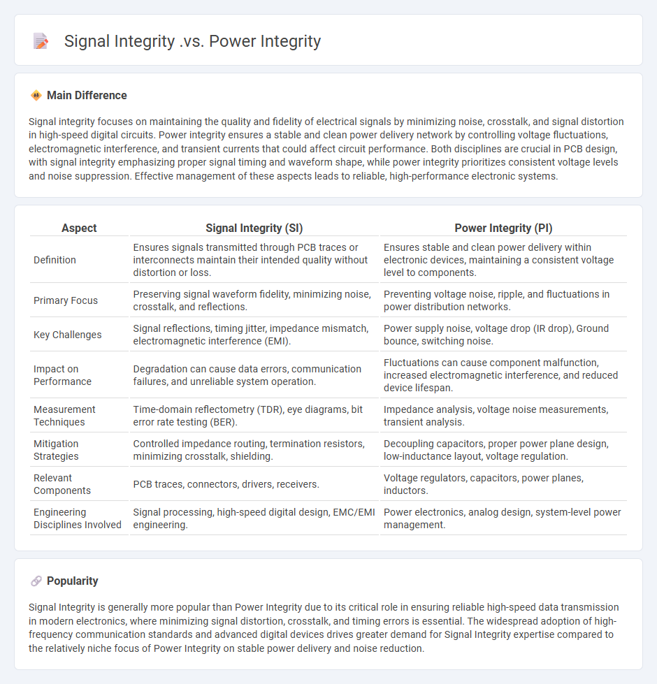
Signal integrity focuses on maintaining the quality and fidelity of electrical signals by minimizing noise, crosstalk, and signal distortion in high-speed digital circuits. Power integrity ensures a stable and clean power delivery network by controlling voltage fluctuations, electromagnetic interference, and transient currents that could affect circuit performance. Both disciplines are crucial in PCB design, with signal integrity emphasizing proper signal timing and waveform shape, while power integrity prioritizes consistent voltage levels and noise suppression. Effective management of these aspects leads to reliable, high-performance electronic systems.
Connection
Signal integrity (SI) and power integrity (PI) are interconnected as both focus on maintaining signal quality and stable voltage levels in electronic circuits. Poor power integrity can cause voltage fluctuations that lead to signal integrity issues such as jitter, noise, and crosstalk. Effective PCB design, including proper decoupling and power distribution network planning, ensures both SI and PI are optimized to prevent data errors and device malfunction.
Comparison Table
| Aspect | Signal Integrity (SI) | Power Integrity (PI) |
|---|---|---|
| Definition | Ensures signals transmitted through PCB traces or interconnects maintain their intended quality without distortion or loss. | Ensures stable and clean power delivery within electronic devices, maintaining a consistent voltage level to components. |
| Primary Focus | Preserving signal waveform fidelity, minimizing noise, crosstalk, and reflections. | Preventing voltage noise, ripple, and fluctuations in power distribution networks. |
| Key Challenges | Signal reflections, timing jitter, impedance mismatch, electromagnetic interference (EMI). | Power supply noise, voltage drop (IR drop), Ground bounce, switching noise. |
| Impact on Performance | Degradation can cause data errors, communication failures, and unreliable system operation. | Fluctuations can cause component malfunction, increased electromagnetic interference, and reduced device lifespan. |
| Measurement Techniques | Time-domain reflectometry (TDR), eye diagrams, bit error rate testing (BER). | Impedance analysis, voltage noise measurements, transient analysis. |
| Mitigation Strategies | Controlled impedance routing, termination resistors, minimizing crosstalk, shielding. | Decoupling capacitors, proper power plane design, low-inductance layout, voltage regulation. |
| Relevant Components | PCB traces, connectors, drivers, receivers. | Voltage regulators, capacitors, power planes, inductors. |
| Engineering Disciplines Involved | Signal processing, high-speed digital design, EMC/EMI engineering. | Power electronics, analog design, system-level power management. |
Transmission Line Effects
Transmission line effects significantly impact the performance of high-frequency circuits in engineering applications by causing signal distortion, attenuation, and delay. These effects arise when the physical length of conductors approaches a substantial fraction of the signal wavelength, leading to reflections and impedance mismatches. Engineers utilize techniques such as impedance matching, proper termination, and controlled impedance PCB design to mitigate these issues and ensure signal integrity. Accurate modeling through transmission line theory enables effective analysis and optimization of signal propagation in complex electrical systems.
Noise Margins
Noise margins in engineering quantify the tolerance of digital circuits to voltage variations, ensuring reliable operation despite electrical noise. They specify the difference between actual signal levels and the minimum or maximum voltage thresholds defined by logic families such as TTL or CMOS. Higher noise margins improve immunity to interference and signal degradation, critical in high-speed or long-distance data transmission systems. Accurate calculation of noise margins involves analyzing input/output voltage levels and considering environmental factors affecting signal integrity.
Power Distribution Network (PDN)
A Power Distribution Network (PDN) delivers electrical power from substations to end-users, ensuring consistent voltage levels and minimizing power losses. Key components include transformers, distribution lines, circuit breakers, and protective devices that maintain system reliability and safety. Modern PDNs integrate smart grid technologies such as real-time monitoring, automated fault detection, and demand response to enhance efficiency and resilience. Optimization of PDNs involves load balancing, voltage regulation, and harmonic mitigation to support the growing demand for renewable energy sources and electric vehicles.
Crosstalk
Crosstalk in engineering refers to the unwanted transfer of signals between communication channels, causing interference and signal degradation. It commonly occurs in electrical circuits, telecommunications, and PCB designs where closely spaced conductors allow electromagnetic coupling. Minimizing crosstalk involves techniques like increasing wire spacing, shielding, and using differential signaling to enhance signal integrity. Effective crosstalk mitigation is essential for maintaining data accuracy and reducing noise in high-speed data transmission systems.
Voltage Ripple
Voltage ripple refers to the residual periodic variation of the direct current (DC) voltage within power supplies, primarily caused by incomplete suppression of the alternating current (AC) components after rectification. In engineering applications, minimizing voltage ripple is critical to ensure stable and reliable performance of electronic circuits, especially in sensitive analog and digital systems. Power supply designers often employ smoothing capacitors, inductors, and voltage regulators to reduce ripple voltage to acceptable levels, typically measured in millivolts (mV). Accurate ripple reduction improves power quality and enhances the lifespan and efficiency of electrical devices.
Source and External Links
Signal and Power Integrity - Lesson 2 - Power Integrity (PI) ensures a stable and noise-free power delivery to components, which directly affects Signal Integrity (SI) by preventing supply noise and ground bounce that degrade signal quality and cause data errors.
What is Signal Integrity? - Signal Integrity concerns the fidelity of signals on a PCB--ensuring signals arrive accurately without distortion, while Power Integrity focuses on the quality of power delivered to components, both requiring careful simulation as changes in one can impact the other.
What's The Difference Between Signal Integrity And Power Integrity - Signal Integrity deals with impedance matching of signal traces to preserve signal quality, whereas Power Integrity aims to minimize impedance in the power distribution network to maintain stable power delivery; both are interrelated but focus on different physical aspects of circuit behavior.
FAQs
What is signal integrity in electronics?
Signal integrity in electronics refers to the measure of the quality and reliability of electrical signals as they travel through a circuit, ensuring minimal distortion, noise, and interference to maintain accurate data transmission.
What is power integrity in electronic circuits?
Power integrity in electronic circuits ensures stable and noise-free voltage delivery to all components by managing power distribution, minimizing voltage drops, and reducing electromagnetic interference.
How do signal integrity and power integrity differ?
Signal integrity focuses on maintaining the quality and fidelity of electrical signals within a circuit to prevent distortion and errors, while power integrity ensures stable and clean power delivery to electronic components, minimizing voltage fluctuations and noise.
Why is signal integrity important for high-speed design?
Signal integrity is crucial for high-speed design because it ensures accurate data transmission by minimizing issues like signal degradation, crosstalk, reflections, and electromagnetic interference, which can cause data errors, timing problems, and system failures.
What factors affect power integrity in a PCB?
Power integrity in a PCB is affected by factors such as power supply noise, voltage drops, impedance of power distribution networks, decoupling capacitor placement, PCB layout and layer stacking, current return paths, and electromagnetic interference (EMI).
How do problems in power integrity impact signal integrity?
Power integrity issues cause voltage fluctuations and noise that induce timing errors, jitter, and crosstalk, thereby degrading overall signal integrity.
What are best practices for maintaining both signal and power integrity?
Use controlled impedance PCB traces, proper grounding techniques, and decoupling capacitors to maintain signal and power integrity. Separate power and signal layers, minimize loop areas, and implement differential signaling for noise reduction. Perform thorough simulation and testing to ensure design reliability.