Yagi-Uda antennas excel in high gain and directivity, making them ideal for fixed-frequency applications such as television reception and amateur radio. Log-periodic antennas offer a wide bandwidth and consistent performance across multiple frequencies, suited for applications like communication systems and signal scanning. Explore the detailed differences in design, application, and performance to determine the best choice for your needs.
Main Difference
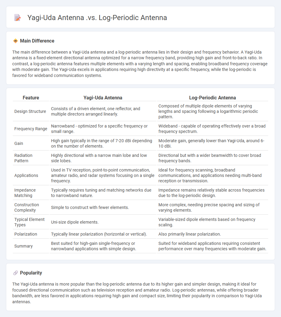
The main difference between a Yagi-Uda antenna and a log-periodic antenna lies in their design and frequency behavior. A Yagi-Uda antenna is a fixed-element directional antenna optimized for a narrow frequency band, providing high gain and front-to-back ratio. In contrast, a log-periodic antenna features multiple elements with a varying length and spacing, enabling broadband frequency coverage with moderate gain. The Yagi-Uda excels in applications requiring high directivity at a specific frequency, while the log-periodic is favored for wideband communication systems.
Connection
Yagi-Uda and log-periodic antennas both serve as directional antennas used primarily for TV reception and communication systems, but they differ in design and frequency behavior. The Yagi-Uda antenna features a fixed number of elements tuned to a narrow frequency range, offering high gain and directivity, while the log-periodic antenna comprises multiple elements with varying lengths and spacings to provide broad frequency coverage and consistent performance across that range. Both antennas rely on parasitic elements to shape radiation patterns, linking their operational principles in antenna technology.
Comparison Table
| Feature | Yagi-Uda Antenna | Log-Periodic Antenna |
|---|---|---|
| Design Structure | Consists of a driven element, one reflector, and multiple directors arranged linearly. | Composed of multiple dipole elements of varying lengths and spacing following a logarithmic periodic pattern. |
| Frequency Range | Narrowband - optimized for a specific frequency or small range. | Wideband - capable of operating effectively over a broad frequency spectrum. |
| Gain | High gain typically in the range of 7-20 dBi depending on the number of elements. | Moderate gain, generally lower than Yagi-Uda, around 6-10 dBi. |
| Radiation Pattern | Highly directional with a narrow main lobe and low side lobes. | Directional but with a wider beamwidth to cover broad frequency bands. |
| Applications | Used in TV reception, point-to-point communication, amateur radio, and radar systems focusing on a single frequency. | Ideal for frequency scanning, broadband communications, and applications needing multi-band reception or transmission. |
| Impedance Matching | Typically requires tuning and matching networks due to narrowband nature. | Impedance remains relatively stable across frequencies due to the log-periodic design. |
| Construction Complexity | Simple to construct with fewer elements. | More complex, needing precise spacing and sizing of varying elements. |
| Typical Element Types | Uni-size dipole elements. | Variable-sized dipole elements based on frequency scaling. |
| Polarization | Typically linear polarization (horizontal or vertical). | Also primarily linear polarization. |
| Summary | Best suited for high-gain single-frequency or narrowband applications with simple design. | Suited for wideband applications requiring consistent performance over many frequencies with moderate gain. |
Directive Gain
Directive gain in engineering refers to a key antenna parameter measuring the concentration of radiated power in a specific direction compared to an isotropic source. It is expressed as a dimensionless ratio or in decibels (dBi) and influences the antenna's ability to transmit or receive signals effectively over distance. High directive gain improves signal strength and reduces interference by focusing energy into a narrow beamwidth, essential for applications such as radar, satellite communication, and wireless networks. Antenna design techniques like using parabolic reflectors or phased arrays optimize directive gain for enhanced performance in targeted directions.
Frequency Bandwidth
Frequency bandwidth in engineering refers to the range of frequencies within a given band that a system, such as a communication channel or electronic device, can effectively transmit or process. It is measured in hertz (Hz) and dictates the capacity and speed of data transmission in applications like wireless communication, signal processing, and audio engineering. A wider bandwidth allows for higher data rates and improved signal fidelity, essential in technologies such as 5G networks and high-definition broadcasting. Precise bandwidth management ensures optimal performance and minimizes interference in complex engineering systems.
Element Spacing
Element spacing in engineering refers to the precise distance maintained between structural or mechanical components to ensure optimal performance, safety, and durability. Proper element spacing minimizes stress concentration, prevents mechanical interference, and facilitates effective load distribution across the structure. Standards such as the American Institute of Steel Construction (AISC) and International Organization for Standardization (ISO) provide guidelines on element spacing to achieve compliance with safety and quality requirements. Accurate calculation and adherence to element spacing parameters are critical in fields like civil engineering, mechanical design, and electronics manufacturing.
Radiation Pattern
Radiation pattern in engineering describes the spatial distribution of energy radiated by an antenna or acoustic source, crucial for optimizing signal directionality and strength. Key parameters include main lobe width, side lobes, and null points, which impact the efficiency and coverage area of communication systems. Patterns are often represented graphically in polar or Cartesian coordinates to visualize power intensity relative to angle. Advanced engineering applications use these patterns to enhance wireless network performance, radar detection, and satellite communication accuracy.
Application Suitability
Application suitability in engineering evaluates how well a material, component, or system meets specific project requirements including strength, durability, and environmental conditions. Engineers analyze factors such as thermal resistance, load capacity, and corrosion behavior to ensure optimal performance and safety. Advanced computer simulations and testing methods like finite element analysis (FEA) assist in predicting application outcomes, reducing risks and costs. Selecting suitable materials and technologies enhances efficiency, longevity, and compliance with industry standards like ASTM and ISO.
Source and External Links
What's the difference between Yagi antennas and log-periodic antennas - Yagi antennas offer high gain and directionality but over a narrow frequency range, while log-periodic antennas provide consistent performance over a wide frequency range at somewhat lower gain, making each suitable for different communication needs.
Log Periodic Antenna Design Essentials - Log periodic antennas excel at broadband coverage across wide frequency ranges and applications like cellular networks and satellite communication owing to their frequency-independent design and versatility.
Yagi Antenna vs Log-periodic Antenna - Sanny Telecom - Yagi antennas are larger, highly directional antennas optimized for picking up signals from one direction, whereas log-periodic antennas are smaller, compact, and can receive signals from multiple directions over a broad frequency range.
FAQs
What is a Yagi-Uda antenna?
A Yagi-Uda antenna is a directional radio antenna consisting of a driven element, a reflector, and multiple parasitic directors, commonly used for television reception and amateur radio.
What is a Log-Periodic antenna?
A Log-Periodic antenna is a directional antenna designed with elements spaced and sized according to a logarithmic function, enabling wide bandwidth and consistent performance across a broad range of frequencies.
What are the key differences between Yagi-Uda and Log-Periodic antennas?
Yagi-Uda antennas feature fixed element lengths and spacing optimized for narrowband, high-gain directional radiation, while Log-Periodic antennas have elements with gradually varying lengths and spacing to provide wideband frequency coverage with moderate gain and consistent impedance.
How does the frequency range of a Yagi-Uda compare to a Log-Periodic antenna?
A Yagi-Uda antenna offers a narrow frequency range optimized for specific frequencies, while a Log-Periodic antenna provides a wide frequency range covering multiple bands with consistent performance.
Which antenna provides better directivity and gain?
A parabolic reflector antenna provides better directivity and gain compared to other antenna types.
Where are Yagi-Uda and Log-Periodic antennas commonly used?
Yagi-Uda antennas are commonly used in television reception, amateur radio, and point-to-point communications; Log-Periodic antennas are widely used for broadband applications such as TV antennas, HF communications, and electromagnetic interference testing.
How does the construction of a Yagi-Uda differ from a Log-Periodic antenna?
A Yagi-Uda antenna features a fixed set of parasitic elements--one driven element, several directors, and typically one reflector--designed for a specific frequency, whereas a Log-Periodic antenna consists of multiple driven elements with gradually varying lengths and spacing to operate efficiently over a wide frequency range.