Slip ring induction motors feature external rotor windings connected through slip rings, enabling adjustable starting torque and speed control, ideal for heavy-load applications. Squirrel cage induction motors have rotor bars short-circuited within a laminated core, offering rugged construction, low maintenance, and high efficiency for constant speed operations. Explore further to understand the distinct advantages and applications of each motor type.
Main Difference
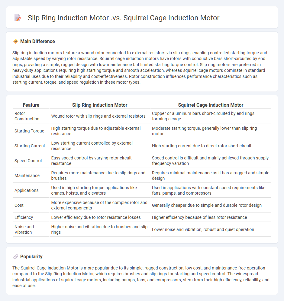
Slip ring induction motors feature a wound rotor connected to external resistors via slip rings, enabling controlled starting torque and adjustable speed by varying rotor resistance. Squirrel cage induction motors have rotors with conductive bars short-circuited by end rings, providing a simple, rugged design with low maintenance but limited starting torque control. Slip ring motors are preferred in heavy-duty applications requiring high starting torque and smooth acceleration, whereas squirrel cage motors dominate in standard industrial uses due to their reliability and cost-effectiveness. Rotor construction influences performance characteristics such as starting current, torque, and speed regulation in these motor types.
Connection
Slip ring induction motors are connected using external resistors linked to the rotor windings via slip rings, allowing control of starting current and torque. Squirrel cage induction motors have rotor bars short-circuited within the rotor core, eliminating the need for external connections and making them simpler and more robust. The stator windings in both motor types are connected to the power supply, but rotor circuit access differentiates their connection and control methods.
Comparison Table
| Feature | Slip Ring Induction Motor | Squirrel Cage Induction Motor |
|---|---|---|
| Rotor Construction | Wound rotor with slip rings and external resistors | Copper or aluminum bars short-circuited by end rings forming a cage |
| Starting Torque | High starting torque due to adjustable external resistance | Moderate starting torque, generally lower than slip ring motor |
| Starting Current | Low starting current controlled by external resistance | High starting current due to direct rotor short circuit |
| Speed Control | Easy speed control by varying rotor circuit resistance | Speed control is difficult and mainly achieved through supply frequency variation |
| Maintenance | Requires more maintenance due to slip rings and brushes | Requires minimal maintenance as it has a rugged and simple design |
| Applications | Used in high starting torque applications like cranes, hoists, and elevators | Used in applications with constant speed requirements like fans, pumps, and compressors |
| Cost | More expensive because of the complex rotor and external components | Generally cheaper due to simple and durable rotor design |
| Efficiency | Lower efficiency due to rotor resistance losses | Higher efficiency because of less rotor resistance |
| Noise and Vibration | Higher noise and vibration due to brushes and slip rings | Lower noise and vibration, robust and quiet operation |
Rotor Construction
Rotor construction in engineering focuses on designing rotating components that convert energy efficiently in machines such as turbines, electric motors, and generators. High-strength materials like steel alloys and composite fibers are employed to withstand centrifugal forces and thermal stresses during operation. Advanced manufacturing techniques, including precision casting and additive manufacturing, enhance rotor balance and durability. Optimizing aerodynamic blade profiles improves performance and reduces energy losses in turbines and compressors.
Starting Torque
Starting torque refers to the torque generated by an engine or motor at zero or low rotational speed, crucial for initiating motion in mechanical systems. It depends on factors such as motor design, current flow, and load inertia, directly impacting the ability of devices like electric motors and internal combustion engines to overcome static friction and inertia. In induction motors, starting torque is typically lower than running torque, necessitating methods such as using a star-delta starter or inverter drives to enhance performance. Precise calculation and optimization of starting torque ensure efficient operation and prevent mechanical failure in industrial applications.
Speed Control
Speed control in engineering involves regulating the rotational velocity of machines such as electric motors, engines, and turbines for optimized performance and efficiency. Techniques include variable frequency drives (VFDs) for AC motors, pulse-width modulation (PWM) for DC motors, and mechanical governors in combustion engines. Precise speed control enhances energy efficiency, reduces wear and tear, and ensures consistent output in manufacturing processes. Advanced systems incorporate feedback sensors like encoders and tachometers to maintain stable speeds under varying load conditions.
Maintenance Requirements
Maintenance requirements in engineering focus on ensuring equipment reliability and performance through scheduled inspections, preventive repairs, and condition monitoring. Implementing predictive maintenance strategies using sensors and IoT technology reduces downtime and extends asset lifespan. Compliance with industry standards such as ISO 55000 enhances asset management efficiency and safety. Effective maintenance management lowers operational costs and improves overall system availability.
Industrial Applications
Industrial applications in engineering encompass the design, development, and optimization of machinery, systems, and processes across sectors such as manufacturing, automotive, aerospace, and energy. Precise engineering techniques enable enhanced production efficiency, quality control, and sustainability by integrating automation, robotics, and advanced materials. Technologies like computer-aided design (CAD), finite element analysis (FEA), and Internet of Things (IoT) sensors play critical roles in predictive maintenance and performance monitoring. Engineering principles applied to industrial processes contribute significantly to reducing operational costs and minimizing environmental impact.
Source and External Links
Difference Between Squirrel Cage and Slip Ring - Grand - The primary difference is in their rotor construction and operation: the squirrel cage rotor is simple, rugged, with bars shorted by end rings, while the slip ring rotor has windings connected to external resistors via slip rings and brushes, allowing adjustable rotor resistance for better control and starting performance.
Difference Between Slip Ring and Squirrel Cage Induction Motor - Tutorialspoint - Slip ring motors provide high starting torque with low starting current due to external rotor resistance, have brushes requiring more maintenance, and allow speed control; squirrel cage motors have a simple construction, low starting torque, high starting current, less maintenance, higher efficiency, and generally lower cost but limited speed control.
Squirrel Cage vs Wound Rotor (Slip Ring) Induction Motor - YouTube - Slip ring motors are suited to applications requiring high starting torque and variable speed such as cranes and elevators due to their wound rotor and external resistance, while squirrel cage motors are ideal for constant speed applications like fans and pumps because of their simple, rugged rotor.
FAQs
What is an induction motor?
An induction motor is an electric motor that operates on electromagnetic induction, where a rotating magnetic field in the stator induces current in the rotor, causing it to spin without direct electrical connection.
What is a slip ring induction motor?
A slip ring induction motor is an AC motor with a wound rotor containing slip rings that allow external resistors to control starting current and torque.
What is a squirrel cage induction motor?
A squirrel cage induction motor is an AC electric motor featuring a rotor composed of conductive bars short-circuited by end rings, forming a cage-like structure that induces current and generates torque through electromagnetic induction.
How do slip ring and squirrel cage induction motors differ in construction?
Slip ring induction motors feature a rotor with windings connected to external slip rings for variable resistance control; squirrel cage induction motors have a rotor composed of aluminum or copper bars short-circuited by end rings, forming a cage-like structure without external connections.
What are the typical applications of slip ring and squirrel cage induction motors?
Slip rings are typically used in applications requiring high starting torque and variable speed control, such as cranes, hoists, conveyors, and large pumps. Squirrel cage induction motors are commonly applied in industrial machinery, fans, blowers, compressors, and household appliances due to their rugged design and low maintenance.
What are the advantages of a slip ring induction motor over a squirrel cage induction motor?
Slip ring induction motors offer high starting torque, adjustable starting current via external resistors, smoother start and speed control, and better overload capacity compared to squirrel cage induction motors.
Why is a squirrel cage induction motor more commonly used than a slip ring induction motor?
A squirrel cage induction motor is more commonly used because it has a simpler, rugged construction, lower maintenance requirements, higher efficiency, better reliability, and lower initial cost compared to a slip ring induction motor.