BJTs (Bipolar Junction Transistors) and MOSFETs (Metal-Oxide-Semiconductor Field-Effect Transistors) differ fundamentally in operation, with BJTs being current-controlled devices and MOSFETs voltage-controlled. BJTs offer high gain and faster switching speeds, making them suitable for analog applications, while MOSFETs provide higher input impedance and lower power consumption, ideal for digital circuits. Explore more to understand their specific use cases and performance characteristics.
Main Difference
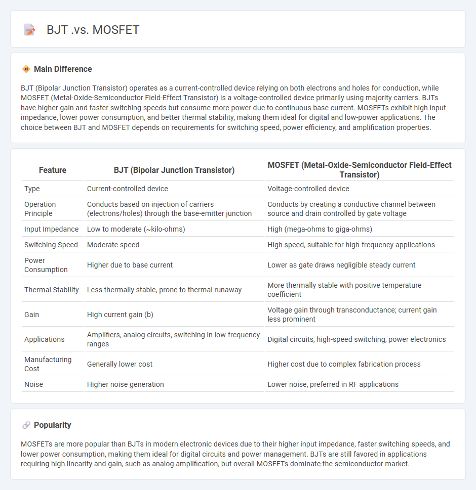
BJT (Bipolar Junction Transistor) operates as a current-controlled device relying on both electrons and holes for conduction, while MOSFET (Metal-Oxide-Semiconductor Field-Effect Transistor) is a voltage-controlled device primarily using majority carriers. BJTs have higher gain and faster switching speeds but consume more power due to continuous base current. MOSFETs exhibit high input impedance, lower power consumption, and better thermal stability, making them ideal for digital and low-power applications. The choice between BJT and MOSFET depends on requirements for switching speed, power efficiency, and amplification properties.
Connection
BJT and MOSFET are often connected in circuits as complementary devices to leverage their distinct switching and amplification properties, commonly found in CMOS and BiCMOS technologies. In such configurations, the BJT typically serves as the current amplifier due to its high gain, while the MOSFET provides voltage control with high input impedance, enabling efficient switching. This connection enhances overall performance in analog and digital circuits by combining the advantages of bipolar junction transistors and metal-oxide-semiconductor field-effect transistors.
Comparison Table
| Feature | BJT (Bipolar Junction Transistor) | MOSFET (Metal-Oxide-Semiconductor Field-Effect Transistor) |
|---|---|---|
| Type | Current-controlled device | Voltage-controlled device |
| Operation Principle | Conducts based on injection of carriers (electrons/holes) through the base-emitter junction | Conducts by creating a conductive channel between source and drain controlled by gate voltage |
| Input Impedance | Low to moderate (~kilo-ohms) | High (mega-ohms to giga-ohms) |
| Switching Speed | Moderate speed | High speed, suitable for high-frequency applications |
| Power Consumption | Higher due to base current | Lower as gate draws negligible steady current |
| Thermal Stability | Less thermally stable, prone to thermal runaway | More thermally stable with positive temperature coefficient |
| Gain | High current gain (b) | Voltage gain through transconductance; current gain less prominent |
| Applications | Amplifiers, analog circuits, switching in low-frequency ranges | Digital circuits, high-speed switching, power electronics |
| Manufacturing Cost | Generally lower cost | Higher cost due to complex fabrication process |
| Noise | Higher noise generation | Lower noise, preferred in RF applications |
Current-Controlled vs. Voltage-Controlled Device
Current-controlled devices regulate output parameters by adjusting input current, commonly seen in bipolar junction transistors (BJTs) where the collector current depends on the base current. Voltage-controlled devices, such as field-effect transistors (FETs), operate by modulating output characteristics through input voltage variations. Current control offers precise amplification in analog circuits, while voltage control facilitates high input impedance and low power consumption. Selecting between these device types depends on application requirements like switching speed, linearity, and power efficiency.
Input Impedance
Input impedance in engineering refers to the measure of opposition that a circuit or device presents to incoming electrical signals at its input terminals, expressed in ohms (O). It determines how much current will flow into the device when a voltage is applied and is critical for maximizing signal transfer and minimizing reflections in systems such as amplifiers, antennas, and transmission lines. Typical input impedance values vary widely; for example, audio equipment often targets 10 kO to 100 kO, while radio frequency circuits may range from 50 O to 75 O for optimal matching. Accurate impedance matching improves overall system performance and prevents signal degradation in communication and signal processing applications.
Switching Speed
Switching speed in engineering refers to the time required for a device, such as a transistor or relay, to transition from one state to another, typically measured in nanoseconds or microseconds. High switching speeds are critical for optimizing the performance of digital circuits, enabling faster data processing and communication. Advances in semiconductor technology, like silicon carbide (SiC) and gallium nitride (GaN) materials, have significantly enhanced switching speeds in power electronics. Engineers prioritize switching speed to reduce power loss, improve efficiency, and achieve higher frequency operation in applications ranging from microprocessors to power converters.
Power Efficiency
Power efficiency in engineering measures how effectively electrical power is converted into usable output without excessive energy loss. High power efficiency reduces operational costs and minimizes environmental impact by lowering energy consumption and heat generation. Engineers optimize power efficiency through advanced materials, circuit design improvements, and energy recovery systems. Modern applications in renewable energy and electric vehicles prioritize efficiency rates above 90% to enhance performance and sustainability.
Typical Applications
Engineering applications commonly include structural analysis, mechanical system design, and electrical circuit optimization. Finite element analysis (FEA) is widely used to model stress distribution in bridges and aircraft components. Control systems engineering applies feedback mechanisms to enhance automation in manufacturing and robotics. Computational fluid dynamics (CFD) plays a crucial role in aerodynamic testing and environmental engineering projects.
Source and External Links
MOSFET vs. Transistor (BJT) - DomoticX - MOSFETs are voltage-controlled devices with terminals source, drain, and gate ideal for high-power applications, while BJTs are current-controlled devices with base, emitter, and collector terminals, commonly used in low-current applications and depend on base current for operation.
Difference between BJT and MOSFET - Tutorials Point - BJTs are three-terminal bipolar transistors relying on both electron and hole carriers for current, used for switching and amplification; MOSFETs are four-terminal field-effect transistors controlled by voltage at the gate, designed for high-speed, low-loss switching.
What's the difference between MOSFET and BJT and how to choose? - MOSFETs are unipolar voltage-controlled devices with high input impedance and better efficiency, generating less heat, suitable for digital and power applications; BJTs are bipolar current-controlled devices preferred for current amplification circuits like motor controllers.
FAQs
What is a BJT?
A Bipolar Junction Transistor (BJT) is a semiconductor device used to amplify or switch electrical signals by controlling current flow through three layers: emitter, base, and collector.
What is a MOSFET?
A MOSFET (Metal-Oxide-Semiconductor Field-Effect Transistor) is a semiconductor device used for switching and amplifying electronic signals in integrated circuits.
How do BJTs and MOSFETs differ?
BJTs are current-controlled devices using bipolar junctions with higher gain and linearity, while MOSFETs are voltage-controlled devices with insulated gates, offering higher input impedance and faster switching speeds.
What are the advantages of BJTs?
BJTs offer high current gain, fast switching speeds, excellent linearity, and robustness in high-frequency applications.
What are the advantages of MOSFETs?
MOSFETs offer high input impedance, fast switching speed, low power consumption, excellent thermal stability, and scalability for integrated circuits.
Where are BJTs commonly used?
BJTs are commonly used in amplification circuits, switching applications, and signal processing devices.
Where are MOSFETs commonly used?
MOSFETs are commonly used in power supplies, amplifiers, switching regulators, motor controllers, and digital circuits such as microprocessors and memory devices.