Orthogonal cutting involves a cutting edge perpendicular to the cutting direction, resulting in simpler chip formation and force analysis, ideal for precision machining of metals. Oblique cutting features the cutting edge angled relative to the cutting direction, producing a helical chip flow and reducing cutting forces, commonly used in turning and milling operations. Explore the detailed mechanics and applications of orthogonal versus oblique cutting to enhance machining efficiency.
Main Difference
Orthogonal cutting involves a cutting edge perpendicular to the cutting direction, resulting in a two-dimensional cutting process with a single shear plane. Oblique cutting features a cutting edge at an angle to the cutting direction, causing a three-dimensional cutting action and multiple shear planes. Orthogonal cutting typically produces less tool wear and simpler chip formation, while oblique cutting enhances surface finish and reduces cutting forces. The choice depends on machining goals, with orthogonal cutting preferred for simplicity and oblique cutting for efficiency and surface quality.
Connection
Orthogonal cutting and oblique cutting are interconnected machining processes distinguished by the angle between the cutting edge and the cutting velocity vector, with orthogonal cutting featuring a 90-degree angle and oblique cutting an acute angle. Both methods influence chip formation, cutting forces, and surface finish, but oblique cutting generally produces a helical chip flow and reduced cutting forces due to the angled engagement. Understanding their relationship is crucial for optimizing tool design, machining parameters, and material removal rates in manufacturing operations.
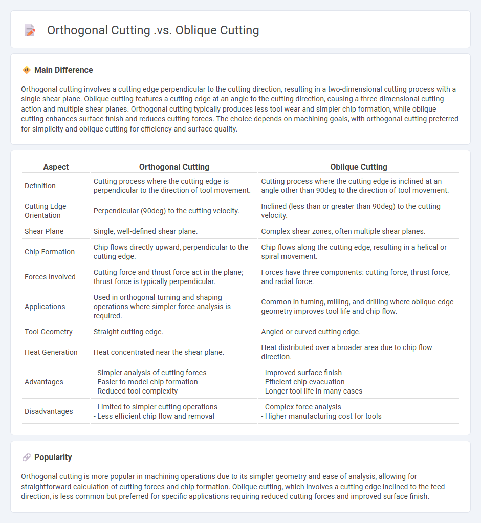
Comparison Table
| Aspect | Orthogonal Cutting | Oblique Cutting |
|---|---|---|
| Definition | Cutting process where the cutting edge is perpendicular to the direction of tool movement. | Cutting process where the cutting edge is inclined at an angle other than 90deg to the direction of tool movement. |
| Cutting Edge Orientation | Perpendicular (90deg) to the cutting velocity. | Inclined (less than or greater than 90deg) to the cutting velocity. |
| Shear Plane | Single, well-defined shear plane. | Complex shear zones, often multiple shear planes. |
| Chip Formation | Chip flows directly upward, perpendicular to the cutting edge. | Chip flows along the cutting edge, resulting in a helical or spiral movement. |
| Forces Involved | Cutting force and thrust force act in the plane; thrust force is typically perpendicular. | Forces have three components: cutting force, thrust force, and radial force. |
| Applications | Used in orthogonal turning and shaping operations where simpler force analysis is required. | Common in turning, milling, and drilling where oblique edge geometry improves tool life and chip flow. |
| Tool Geometry | Straight cutting edge. | Angled or curved cutting edge. |
| Heat Generation | Heat concentrated near the shear plane. | Heat distributed over a broader area due to chip flow direction. |
| Advantages |
- Simpler analysis of cutting forces - Easier to model chip formation - Reduced tool complexity |
- Improved surface finish - Efficient chip evacuation - Longer tool life in many cases |
| Disadvantages |
- Limited to simpler cutting operations - Less efficient chip flow and removal |
- Complex force analysis - Higher manufacturing cost for tools |
Cutting Angle
Cutting angle in engineering refers to the angle formed between the cutting edge of a tool and the workpiece surface during machining. Optimizing the cutting angle improves tool life, surface finish, and cutting efficiency by minimizing friction and heat generation. Common cutting angles include rake, clearance, and approach angles, each influencing chip formation and cutting forces. Precise selection and adjustment of cutting angles are essential for various materials and cutting conditions in manufacturing processes.
Chip Flow Direction
Chip flow direction significantly impacts machining efficiency and surface finish quality in engineering. Controlling the chip flow helps reduce tool wear, prevents workpiece damage, and optimizes cutting force distribution. Advanced CNC machines utilize toolpath strategies that precisely dictate chip flow direction to maximize material removal rates and improve dimensional accuracy. Understanding chip flow dynamics is critical in industries such as aerospace and automotive manufacturing, where precision and reliability are paramount.
Tool Engagement
Tool engagement in engineering refers to the precise interaction between a cutting tool and the workpiece during machining processes. Optimizing factors such as cutting speed, feed rate, and tool geometry enhances material removal efficiency and surface finish quality. Accurate tool engagement reduces tool wear and energy consumption, contributing to longer tool life and cost-effective manufacturing. Advanced monitoring systems and adaptive controls enable real-time adjustments, ensuring consistent machining performance in complex engineering applications.
Force Distribution
Force distribution in engineering refers to how loads and stresses are spread across structural elements to ensure stability and prevent failure. Effective force distribution is critical in designing beams, trusses, and foundations, enabling them to bear weight safely under various conditions. Structural engineers use principles of mechanics, such as statics and material strength, to analyze and optimize the distribution of forces in bridges, buildings, and machinery. Accurate force distribution improves durability, safety, and efficiency in engineering projects.
Surface Finish
Surface finish in engineering refers to the texture and quality of a material's surface, characterized by parameters such as roughness, waviness, and lay patterns. Common measurement techniques include profilometry and atomic force microscopy, providing precise roughness average (Ra) values essential for assessing product performance. High-quality surface finishes reduce friction, wear, and corrosion in mechanical components, improving functionality and lifespan. Materials like metals, plastics, and ceramics often require specific surface finish standards defined by ISO 4287 and ANSI B46.1 to ensure compatibility with industrial applications.
Source and External Links
Difference between orthogonal and oblique cutting - In orthogonal cutting, the cutting edge is perpendicular to the cutting speed and chip flow is normal to the edge, while in oblique cutting, the edge is inclined, chip flow is angled, and three force components act on the tool instead of two.
Difference Between Orthogonal and Oblique Cutting - Orthogonal cutting features a tool perpendicular to motion, higher concentrated forces, and excellent surface finish, whereas oblique cutting uses an angled tool, distributes forces, and is versatile for various applications.
Types of metal cutting process - Manufacturing Technology - Orthogonal cutting simplifies analysis with two force components and is common in operations like lathe cut-off, while oblique cutting, typical in turning and milling, requires three-dimensional analysis due to an inclined cutting edge.
FAQs
What is orthogonal cutting in machining?
Orthogonal cutting in machining is a process where the cutting edge of the tool is perpendicular to the direction of tool travel, producing a straight chip flow and simplified shear deformation zone.
What defines oblique cutting and how is it different?
Oblique cutting is defined by the cutting edge being set at an angle less than 90 degrees to the direction of tool travel, resulting in a shearing action that reduces cutting forces and produces a smoother surface finish compared to perpendicular or orthogonal cutting.
How do chip formations differ in orthogonal vs. oblique cutting?
Chip formations in orthogonal cutting are typically continuous, segmented, or discontinuous with a clear shear plane perpendicular to the cutting edge; in oblique cutting, chips form with a helical shape due to the angled cutting edge, causing the chip flow direction to be angled relative to the cutting velocity vector.
What are the main advantages of orthogonal cutting?
Orthogonal cutting offers advantages such as simplified analysis due to two-dimensional stress states, improved accuracy in predicting cutting forces, reduced tool wear from uniform cutting conditions, enhanced surface finish, and efficient chip formation control.
What benefits does oblique cutting provide in manufacturing?
Oblique cutting reduces cutting force and power consumption, improves surface finish, extends tool life, and minimizes chip clogging in manufacturing processes.
How do force directions vary between orthogonal and oblique cutting?
In orthogonal cutting, the cutting force acts primarily in a single plane perpendicular to the cutting edge, whereas in oblique cutting, the force components are distributed across multiple planes due to the angled cutting edge, resulting in forces with both normal and tangential directions relative to the cutting surface.
In which applications is orthogonal or oblique cutting preferred?
Orthogonal cutting is preferred in turning and shaping operations for producing smooth finishes and accurate dimensions, while oblique cutting is favored in milling and drilling applications to improve chip flow and reduce cutting forces.