Lagrangian and Eulerian frameworks represent two fundamental approaches in fluid dynamics and continuum mechanics for analyzing motion and deformation. The Lagrangian perspective tracks individual fluid particles over time, capturing detailed displacement and trajectory information, while the Eulerian method focuses on specific points in space, observing how fluid properties change at these fixed locations. Explore the distinctions and applications of these methods to deepen your understanding of dynamic systems.
Main Difference
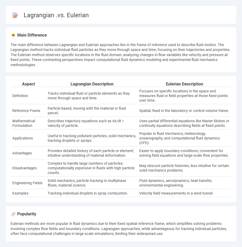
The main difference between Lagrangian and Eulerian approaches lies in the frame of reference used to describe fluid motion. The Lagrangian method tracks individual fluid particles as they move through space and time, focusing on their trajectories and properties. The Eulerian method observes specific locations in the fluid domain, analyzing changes in flow variables like velocity and pressure at fixed points. These contrasting perspectives impact computational fluid dynamics modeling and experimental fluid mechanics methodologies.
Connection
Lagrangian and Eulerian frameworks connect through their complementary perspectives in fluid dynamics, where the Lagrangian approach tracks individual fluid particles' trajectories while the Eulerian method analyzes field variables at fixed spatial points. Mathematical transformations link these descriptions, allowing the conversion of Lagrangian particle paths into Eulerian velocity and pressure fields using coordinate mappings and time-dependent functions. This connection enables comprehensive analysis of fluid motion, combining particle-based insights with spatial flow properties for enhanced modeling and simulation accuracy.
Comparison Table
| Aspect | Lagrangian Description | Eulerian Description |
|---|---|---|
| Definition | Tracks individual fluid or particle elements as they move through space and time. | Focuses on specific locations in the space and measures fluid or field properties at those fixed points over time. |
| Reference Frame | Particle-based, moving with the material or fluid parcel. | Spatial, fixed in the laboratory or control volume frame. |
| Mathematical Formulation | Describes trajectory equations such as dx/dt = velocity of particle. | Uses partial differential equations like Navier-Stokes or continuity equations describing fields at fixed points. |
| Applications | Useful in tracking pollutant particles, solid mechanics, tracking droplets or sprays. | Popular in fluid mechanics, meteorology, oceanography, and computational fluid dynamics (CFD). |
| Advantages | Provides detailed history of each particle or element; intuitive understanding of material deformation. | Easier to apply boundary conditions; convenient for solving field equations and large-scale flow properties. |
| Disadvantages | Complex to handle large numbers of particles; computationally expensive in fluids with high particle counts. | May obscure particle histories; less intuitive for certain solid mechanics problems. |
| Engineering Fields | Solid mechanics, particle tracking in multiphase flows, material science. | Fluid dynamics, aerodynamics, heat transfer, environmental engineering. |
| Examples | Tracking individual droplets in spray combustion. | Velocity field measurements in a wind tunnel. |
Reference Frame
A reference frame in engineering is a coordinate system or set of axes used to measure and describe the position, orientation, and motion of objects within a space. It serves as a basis for analyzing mechanical systems, structural behavior, and dynamics by providing a standardized context for observations. Common types include inertial frames, which do not accelerate, and non-inertial frames, which do accelerate or rotate. Precise definition of reference frames is essential for accurate modeling, simulation, and control of engineering systems.
Particle Tracking
Particle tracking in engineering involves monitoring the movement and behavior of particles within fluid flows or mechanical systems to optimize performance and safety. Techniques such as Particle Image Velocimetry (PIV) and Laser Doppler Anemometry (LDA) provide high-resolution velocity measurements crucial for turbulence analysis and flow visualization. Applications span across aerospace engineering, chemical reactors, and environmental monitoring to improve mixing, reduce wear, and control emissions. Accurate particle trajectory data supports computational fluid dynamics (CFD) model validation, enhancing predictive capabilities in complex engineering scenarios.
Control Volume
Control volume in engineering refers to a defined region in space through which fluid flows, used to analyze mass, momentum, and energy exchanges. It serves as a fundamental concept in fluid mechanics and thermodynamics, enabling engineers to apply conservation laws for system analysis. Control volumes can be fixed or moving and often include boundaries called control surfaces for evaluating fluxes. Accurate control volume analysis supports design optimization in HVAC, aerospace, and chemical processing industries.
Fluid Flow Analysis
Fluid flow analysis examines the behavior of liquids and gases in motion, using principles from fluid mechanics to predict velocity, pressure, and turbulence within various engineering systems. Computational Fluid Dynamics (CFD) tools enable detailed simulations of flow patterns in pipelines, airfoils, and hydraulic machinery, improving design efficiency and performance. Engineers apply fluid flow analysis in sectors such as aerospace, automotive, and civil engineering to optimize energy consumption and reduce environmental impact. Accurate measurement techniques, including Particle Image Velocimetry (PIV) and Laser Doppler Anemometry (LDA), provide critical validation for theoretical and computational models.
Deformation Mapping
Deformation mapping in engineering involves tracking and analyzing changes in material shapes under applied forces using techniques such as finite element analysis (FEA) and digital image correlation (DIC). High-resolution sensors and software tools enable precise measurement of strain and displacement fields, crucial for structural integrity assessments. Applications span aerospace, civil engineering, and automotive industries, where accurate deformation data optimizes design and failure prevention. Advanced deformation mapping technologies also support predictive maintenance by identifying stress concentrations and potential points of material fatigue.
Source and External Links
Lagrangian vs. Eulerian Study of Fluids - This article discusses the key differences between Lagrangian and Eulerian methods in fluid analysis, focusing on tracking individual particles versus analyzing flow patterns at fixed points.
Lagrangian and Eulerian specification of the flow field - This Wikipedia entry explains the Lagrangian and Eulerian specifications by following fluid parcels and observing flow at fixed locations, respectively.
5.1: Lagrangian and Eulerian descriptions - This LibreTexts chapter provides an overview of Lagrangian and Eulerian descriptions, highlighting their application to fluid parcels and field properties like velocity and pressure.
FAQs
What is the Lagrangian approach in fluid dynamics?
The Lagrangian approach in fluid dynamics tracks individual fluid particles' trajectories by following their positions and velocities over time, emphasizing particle-based motion rather than fixed spatial points.
What is the Eulerian approach in fluid dynamics?
The Eulerian approach in fluid dynamics analyzes fluid flow by observing and measuring fluid properties like velocity, pressure, and density at fixed points in space over time.
How do Lagrangian and Eulerian descriptions differ?
Lagrangian description tracks individual fluid particles' trajectories over time, while Eulerian description monitors fluid properties at fixed spatial points.
What are the advantages of the Lagrangian method?
The advantages of the Lagrangian method include simplified handling of complex mechanical systems, effective incorporation of constraints, reduced number of equations compared to Newtonian mechanics, and suitability for both conservative and non-conservative forces.
What are the benefits of using the Eulerian method?
The Eulerian method offers benefits such as simplified modeling of fluid flow in fixed spatial regions, efficient handling of complex boundary conditions, accurate tracking of velocity and pressure fields, and suitability for large-scale computational fluid dynamics simulations.
In which applications is the Lagrangian perspective preferred?
The Lagrangian perspective is preferred in fluid dynamics simulations tracking individual particle trajectories, solid mechanics analyzing material deformation, multiphase flow modeling, and computational methods like smoothed particle hydrodynamics (SPH).
Where is the Eulerian approach most commonly used?
The Eulerian approach is most commonly used in fluid dynamics to analyze the flow field by observing changes at fixed points in space.