Power MOSFETs offer high switching speeds and efficiency in low-voltage applications, while IGBTs excel in handling high-voltage and high-current scenarios with robust thermal performance. Understanding the distinct electrical characteristics and switching behaviors of Power MOSFETs and IGBTs is crucial for optimizing power electronic designs. Explore the detailed comparison to determine the ideal semiconductor device for your specific power application needs.
Main Difference
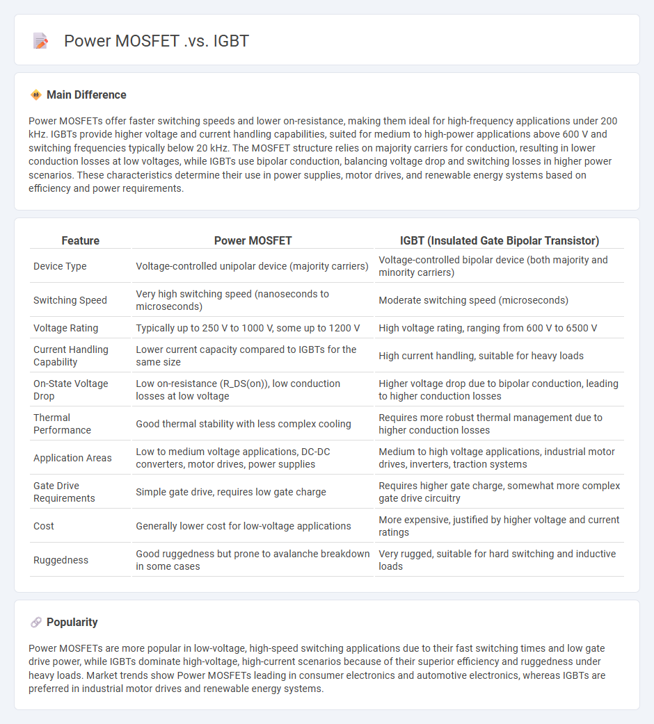
Power MOSFETs offer faster switching speeds and lower on-resistance, making them ideal for high-frequency applications under 200 kHz. IGBTs provide higher voltage and current handling capabilities, suited for medium to high-power applications above 600 V and switching frequencies typically below 20 kHz. The MOSFET structure relies on majority carriers for conduction, resulting in lower conduction losses at low voltages, while IGBTs use bipolar conduction, balancing voltage drop and switching losses in higher power scenarios. These characteristics determine their use in power supplies, motor drives, and renewable energy systems based on efficiency and power requirements.
Connection
Power MOSFETs and IGBTs are often connected in circuits to leverage the high-speed switching capability of MOSFETs and the high voltage, high current handling capacity of IGBTs. In hybrid inverter designs, MOSFETs serve as low-voltage, fast-switching devices while IGBTs manage the high-voltage output stage. This complementary connection improves overall efficiency and performance in power electronics applications such as motor drives and renewable energy systems.
Comparison Table
| Feature | Power MOSFET | IGBT (Insulated Gate Bipolar Transistor) |
|---|---|---|
| Device Type | Voltage-controlled unipolar device (majority carriers) | Voltage-controlled bipolar device (both majority and minority carriers) |
| Switching Speed | Very high switching speed (nanoseconds to microseconds) | Moderate switching speed (microseconds) |
| Voltage Rating | Typically up to 250 V to 1000 V, some up to 1200 V | High voltage rating, ranging from 600 V to 6500 V |
| Current Handling Capability | Lower current capacity compared to IGBTs for the same size | High current handling, suitable for heavy loads |
| On-State Voltage Drop | Low on-resistance (R_DS(on)), low conduction losses at low voltage | Higher voltage drop due to bipolar conduction, leading to higher conduction losses |
| Thermal Performance | Good thermal stability with less complex cooling | Requires more robust thermal management due to higher conduction losses |
| Application Areas | Low to medium voltage applications, DC-DC converters, motor drives, power supplies | Medium to high voltage applications, industrial motor drives, inverters, traction systems |
| Gate Drive Requirements | Simple gate drive, requires low gate charge | Requires higher gate charge, somewhat more complex gate drive circuitry |
| Cost | Generally lower cost for low-voltage applications | More expensive, justified by higher voltage and current ratings |
| Ruggedness | Good ruggedness but prone to avalanche breakdown in some cases | Very rugged, suitable for hard switching and inductive loads |
Switching Speed
Switching speed in engineering refers to the time it takes for a device, such as a transistor or relay, to change from one state to another, typically measured in nanoseconds or microseconds. High switching speeds are crucial in digital circuits and communication systems to ensure fast signal processing and data transmission. Advances in semiconductor technology, like the development of MOSFETs and GaN transistors, have significantly improved switching speeds, enabling higher frequency operations and greater efficiency. Optimizing switching speed impacts power consumption, heat generation, and overall system performance in applications like microprocessors and power electronics.
Voltage Rating
Voltage rating specifies the maximum continuous voltage a component or device can safely withstand without risk of failure or damage. It is a critical parameter in electrical engineering to ensure insulation integrity and prevent dielectric breakdown. Components such as capacitors, transformers, and connectors commonly have voltage ratings defined in volts (V) or kilovolts (kV). Adhering to voltage ratings maximizes reliability and operational safety in electrical and electronic systems.
Conduction Losses
Conduction losses occur when electric current passes through conductors, causing energy dissipation as heat due to the resistance of the material. These losses significantly impact the efficiency of electrical systems such as transformers, power cables, and semiconductor devices. Materials with lower resistivity, such as copper and aluminum, are preferred to minimize conduction losses in engineering applications. Proper thermal management and conductor sizing are critical strategies for reducing conduction losses and enhancing system performance.
Gate Drive Requirements
Efficient gate drive circuits are essential for controlling power semiconductor devices such as MOSFETs and IGBTs, ensuring reliable switching performance in engineering applications. Key requirements include providing sufficient gate voltage levels to fully turn on the device, delivering high peak current to rapidly charge and discharge the gate capacitance, and maintaining isolation between control circuitry and power stages to prevent damage. The gate driver must also support fast switching times to reduce losses and electromagnetic interference in power converters. Robust thermal management and short-circuit protection further enhance the durability and efficiency of gate drive systems in industrial settings.
Application Suitability
Application suitability in engineering refers to the evaluation of whether a specific technology, material, or process meets the required performance criteria for a given project. Factors such as environmental conditions, load capacity, cost-efficiency, and compatibility with existing systems are critical in determining suitability. Standards from organizations like ASTM International and ISO provide benchmarks that guide engineers in assessing application fit. Choosing the appropriate solution improves project outcomes, safety, and longevity of engineering designs.
Source and External Links
MOSFET / IGBT - ADVANCED Motion Controls - MOSFETs are voltage-driven, majority carrier devices suited for high switching frequency and low voltage applications, while IGBTs are current-controlled, minority carrier devices that handle higher voltages and currents but switch slower, making MOSFETs ideal for faster switching and IGBTs better for high power scenarios.
Using IGBT or Mosfet | Forum for Electronics - In practical boost converter designs operating at around 50 kHz and 1.2 kW, MOSFETs often provide lower overall losses due to faster switching, whereas IGBTs are preferred for higher voltage ratings but with higher switching losses.
IGBT vs MOSFET - Bourns - MOSFETs have much lower ON resistance at low voltages making them efficient for high-frequency switching applications (around 100 kHz), while IGBTs excel in high current, low-frequency applications such as AC drives operating below 20 kHz, offering better performance at higher current densities.
FAQs
What is a Power MOSFET?
A Power MOSFET is a metal-oxide-semiconductor field-effect transistor optimized for high current and high voltage switching applications in power electronics.
What is an IGBT?
An IGBT (Insulated Gate Bipolar Transistor) is a semiconductor device used to switch and amplify electrical power efficiently in applications such as inverters, motor drives, and power supplies.
What is the difference between Power MOSFET and IGBT?
Power MOSFETs are voltage-controlled devices offering high switching speed and low conduction losses, ideal for low-voltage, high-frequency applications; IGBTs combine MOSFET input with bipolar transistor output, providing high voltage and current handling with slower switching, suited for medium to high-power applications.
Where are Power MOSFETs used?
Power MOSFETs are used in power supplies, motor controllers, DC-DC converters, automotive electronics, and high-frequency switching applications.
Where are IGBTs used?
IGBTs are used in variable-frequency drives, electric vehicles, industrial motor drives, renewable energy systems like solar inverters, and uninterruptible power supplies (UPS).
How do Power MOSFETs and IGBTs switch?
Power MOSFETs switch by voltage-controlled formation and removal of a conductive channel between the drain and source, using gate voltage to modulate conductivity. IGBTs switch by voltage-controlled injection and removal of charge carriers in the p-n junction, combining MOS gate control with bipolar conduction for efficient current flow.
Which is better: Power MOSFET or IGBT?
Power MOSFETs offer faster switching speeds and lower gate drive power, making them ideal for high-frequency applications, while IGBTs provide higher voltage and current handling capabilities, better suited for high-power, low-frequency applications.