Slip casting and tape casting are two prominent ceramic forming techniques used to shape materials with precision and efficiency. Slip casting involves pouring a liquid clay slip into a porous mold to create complex, hollow shapes, while tape casting produces thin, flat ceramic sheets by spreading slurry onto a moving carrier tape. Explore the distinct advantages, applications, and process details of slip casting and tape casting to understand their roles in advanced ceramic manufacturing.
Main Difference
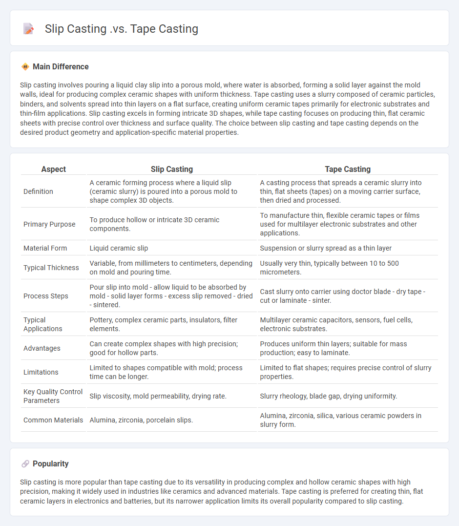
Slip casting involves pouring a liquid clay slip into a porous mold, where water is absorbed, forming a solid layer against the mold walls, ideal for producing complex ceramic shapes with uniform thickness. Tape casting uses a slurry composed of ceramic particles, binders, and solvents spread into thin layers on a flat surface, creating uniform ceramic tapes primarily for electronic substrates and thin-film applications. Slip casting excels in forming intricate 3D shapes, while tape casting focuses on producing thin, flat ceramic sheets with precise control over thickness and surface quality. The choice between slip casting and tape casting depends on the desired product geometry and application-specific material properties.
Connection
Slip casting and tape casting are connected as ceramic fabrication techniques that utilize particle suspensions to create shaped components. Slip casting involves pouring a liquid clay slip into a porous mold to form three-dimensional objects, while tape casting spreads a ceramic slurry into thin, flat layers for producing uniform tapes or sheets. Both methods rely on controlled drying and sintering processes, enabling precise microstructural control in advanced ceramic manufacturing.
Comparison Table
| Aspect | Slip Casting | Tape Casting |
|---|---|---|
| Definition | A ceramic forming process where a liquid slip (ceramic slurry) is poured into a porous mold to shape complex 3D objects. | A casting process that spreads a ceramic slurry into thin, flat sheets (tapes) on a moving carrier surface, then dried and processed. |
| Primary Purpose | To produce hollow or intricate 3D ceramic components. | To manufacture thin, flexible ceramic tapes or films used for multilayer electronic substrates and other applications. |
| Material Form | Liquid ceramic slip | Suspension or slurry spread as a thin layer |
| Typical Thickness | Variable, from millimeters to centimeters, depending on mold and pouring time. | Usually very thin, typically between 10 to 500 micrometers. |
| Process Steps | Pour slip into mold - allow liquid to be absorbed by mold - solid layer forms - excess slip removed - dried - sintered. | Cast slurry onto carrier using doctor blade - dry tape - cut or laminate - sinter. |
| Typical Applications | Pottery, complex ceramic parts, insulators, filter elements. | Multilayer ceramic capacitors, sensors, fuel cells, electronic substrates. |
| Advantages | Can create complex shapes with high precision; good for hollow parts. | Produces uniform thin layers; suitable for mass production; easy to laminate. |
| Limitations | Limited to shapes compatible with mold; process time can be longer. | Limited to flat shapes; requires precise control of slurry properties. |
| Key Quality Control Parameters | Slip viscosity, mold permeability, drying rate. | Slurry rheology, blade gap, drying uniformity. |
| Common Materials | Alumina, zirconia, porcelain slips. | Alumina, zirconia, silica, various ceramic powders in slurry form. |
Slurry Composition
Slurry composition in engineering involves a mixture of solids suspended in a liquid, typically water, to facilitate transport or processing. The particle size distribution, solid concentration, and fluid viscosity are critical parameters influencing flow behavior and efficiency in pipelines or reactors. Common applications include mineral processing, dredging, and waste treatment, where optimizing slurry properties reduces wear on equipment and energy consumption. Advanced modeling techniques and rheological studies assist in designing slurry systems that enhance operational performance and reliability.
Mold Material
Mold materials in engineering predominantly consist of steel alloys such as P20, H13, and S7 due to their excellent strength, toughness, and thermal conductivity properties. These materials withstand high temperatures and pressures during injection molding, die casting, and other manufacturing processes, ensuring durability and dimensional stability. Advanced mold materials also include aluminum alloys for rapid prototyping and epoxy resins for low-volume production. Proper selection of mold material directly influences product quality, cycle time, and overall manufacturing efficiency.
Green Body Thickness
Green body thickness in engineering refers to the initial thickness of a compacted powder before sintering in powder metallurgy processes. Accurate control of green body thickness is critical for achieving desired mechanical properties and dimensional tolerances in the final sintered part. Typical green body thickness ranges from millimeters to several centimeters, depending on the application and material system. Optimizing green body thickness helps minimize shrinkage defects and ensures uniform density throughout the component.
Application Sectors
Engineering applications span diverse sectors including civil, mechanical, electrical, and software engineering. Civil engineering focuses on infrastructure projects such as bridges, roads, and buildings while mechanical engineering drives advancements in automotive, aerospace, and manufacturing industries. Electrical engineering underpins power generation, telecommunications, and control systems, enabling smart grid and IoT innovations. Software engineering supports digital transformation across finance, healthcare, and robotics through development of algorithms, artificial intelligence, and cloud computing platforms.
Dimensional Control
Dimensional control in engineering ensures precise measurement and verification of components to meet design specifications and functional requirements. Advanced technologies such as coordinate measuring machines (CMM), laser scanners, and optical systems provide high accuracy and repeatability in inspecting complex geometries. Effective dimensional control reduces manufacturing errors, improves product quality, and minimizes costly rework by maintaining tight tolerances throughout production. Industries like aerospace, automotive, and precision manufacturing heavily rely on dimensional control systems to uphold stringent quality standards and regulatory compliance.
Source and External Links
Slip and Tape Casting | PDF - Scribd - Slip casting is used for creating complex ceramic shapes by pouring liquid clay into plaster molds, while tape casting produces thin, flat ceramic sheets with precise thickness control using a doctor blade over a moving carrier, typically for electronic applications.
Tape Casting History - Tape casting differs from slip casting primarily in that it uses a non-absorptive carrier surface (often polymer-based) for casting thin ceramic layers, enabling continuous roll-to-roll processing, whereas slip casting involves porous plaster molds to absorb the liquid.
Tape casting - Wikipedia - Tape casting, also known as doctor blading, casts ceramic slurry into thin tapes or sheets on a flat surface and is mainly suited for producing thin films, in contrast to slip casting which forms more complex 3D shapes from liquid clay poured into molds.
FAQs
What is slip casting?
Slip casting is a ceramic forming technique where liquid clay slip is poured into a porous mold, allowing water to be absorbed and a solid layer to form, creating a hollow shaped object.
What is tape casting?
Tape casting is a manufacturing process that produces thin ceramic or metal sheets by spreading a slurry onto a flat surface and drying it to form a flexible green tape.
How does slip casting differ from tape casting?
Slip casting uses a liquid clay slurry poured into a porous mold to form ceramic layers by drainage, while tape casting spreads a ceramic slurry into thin, flexible sheets on a flat surface for fabricating thin, uniform ceramic tapes.
What materials are used in slip casting and tape casting?
Slip casting uses ceramic slips composed of fine ceramic powders (e.g., alumina, silica, kaolin) dispersed in water with binders and deflocculants; tape casting employs ceramic or metal powders mixed with organic binders, plasticizers, solvents, and dispersants to form thin, flexible green tapes.
What are the main applications of slip casting and tape casting?
Slip casting is mainly applied in producing complex-shaped ceramic components like sanitary ware, tiles, and electrical insulators; tape casting is primarily used for manufacturing thin, flat ceramic substrates, such as multilayer electronic circuits and solid oxide fuel cell components.
What are the advantages of slip casting compared to tape casting?
Slip casting offers complex shape production with high dimensional accuracy and homogeneous microstructure, while tape casting excels in creating thin, flat ceramic sheets with uniform thickness.
What are the limitations of tape casting versus slip casting?
Tape casting limits include difficulties in producing thick or complex 3D shapes and slower drying time, whereas slip casting allows for creating intricate 3D geometries but may result in lower surface smoothness and longer processing times.