Pulse-width modulation (PWM) controls signal power by varying the width of pulses, optimizing energy efficiency in applications like motor speed control and LED dimming. Pulse-code modulation (PCM) converts analog signals into digital data through sampling and quantization, crucial for high-fidelity audio and digital communication systems. Explore further to understand the technical distinctions and application advantages of PWM and PCM.
Main Difference
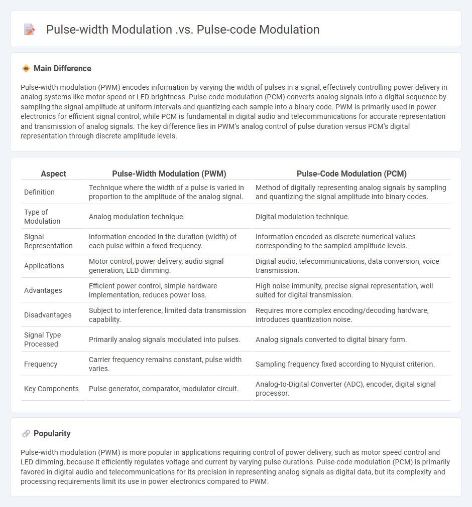
Pulse-width modulation (PWM) encodes information by varying the width of pulses in a signal, effectively controlling power delivery in analog systems like motor speed or LED brightness. Pulse-code modulation (PCM) converts analog signals into a digital sequence by sampling the signal amplitude at uniform intervals and quantizing each sample into a binary code. PWM is primarily used in power electronics for efficient signal control, while PCM is fundamental in digital audio and telecommunications for accurate representation and transmission of analog signals. The key difference lies in PWM's analog control of pulse duration versus PCM's digital representation through discrete amplitude levels.
Connection
Pulse-width modulation (PWM) and pulse-code modulation (PCM) both serve as techniques for encoding information into pulses, with PWM varying the width of pulses to represent analog signal amplitudes, while PCM encodes analog signals into digital binary codes through sample quantization. PWM can be used to generate a modulated signal that approximate analog waveforms, which PCM then converts into a discrete digital representation for processing and transmission. The connection lies in their shared goal of transforming continuous signals into pulse-based formats for efficient communication and control in electronic systems.
Comparison Table
| Aspect | Pulse-Width Modulation (PWM) | Pulse-Code Modulation (PCM) |
|---|---|---|
| Definition | Technique where the width of a pulse is varied in proportion to the amplitude of the analog signal. | Method of digitally representing analog signals by sampling and quantizing the signal amplitude into binary codes. |
| Type of Modulation | Analog modulation technique. | Digital modulation technique. |
| Signal Representation | Information encoded in the duration (width) of each pulse within a fixed frequency. | Information encoded as discrete numerical values corresponding to the sampled amplitude levels. |
| Applications | Motor control, power delivery, audio signal generation, LED dimming. | Digital audio, telecommunications, data conversion, voice transmission. |
| Advantages | Efficient power control, simple hardware implementation, reduces power loss. | High noise immunity, precise signal representation, well suited for digital transmission. |
| Disadvantages | Subject to interference, limited data transmission capability. | Requires more complex encoding/decoding hardware, introduces quantization noise. |
| Signal Type Processed | Primarily analog signals modulated into pulses. | Analog signals converted to digital binary form. |
| Frequency | Carrier frequency remains constant, pulse width varies. | Sampling frequency fixed according to Nyquist criterion. |
| Key Components | Pulse generator, comparator, modulator circuit. | Analog-to-Digital Converter (ADC), encoder, digital signal processor. |
Modulation Technique
Modulation techniques in engineering enable the transmission of information by varying carrier signal properties such as amplitude, frequency, or phase. Common modulation methods include Amplitude Modulation (AM), Frequency Modulation (FM), and Phase Modulation (PM), each suited for specific communication systems like radio broadcasting, telecommunications, and digital data transfer. Advanced techniques such as Quadrature Amplitude Modulation (QAM) and Orthogonal Frequency-Division Multiplexing (OFDM) are integral to modern wireless networks including 4G and 5G standards. Efficient modulation improves signal robustness, bandwidth utilization, and reduces interference in complex communication environments.
Signal Representation
Signal representation in engineering involves the transformation of physical signals into mathematical formats for analysis, processing, and transmission. Commonly used methods include time-domain, frequency-domain, and digital representations, each providing unique insights into signal characteristics. Fourier transforms and wavelet analysis are critical tools for decomposing signals into constituent frequencies and time-frequency components. Accurate signal representation is essential in telecommunications, control systems, and audio processing to enhance system performance and reliability.
Analog vs Digital
Analog engineering processes signals as continuous waveforms, enabling precise representation of real-world phenomena like temperature and sound. Digital engineering converts signals into discrete binary data, facilitating easier processing, storage, and error correction through microprocessors and software algorithms. Analog circuits typically include amplifiers and filters, while digital systems rely on logic gates and microcontrollers. Each approach serves distinct applications--analog excels in audio fidelity, whereas digital dominates computing and communication technologies.
Bandwidth Efficiency
Bandwidth efficiency in engineering refers to the effective use of available frequency spectrum to transmit data signals with minimal waste of bandwidth resources. It is measured in bits per second per Hertz (bps/Hz) and plays a critical role in communication system design, influencing data throughput and signal quality. Advanced modulation techniques like Quadrature Amplitude Modulation (QAM) and Orthogonal Frequency Division Multiplexing (OFDM) are commonly employed to maximize bandwidth efficiency. Enhancing this metric directly contributes to higher network capacity and improved spectral utilization in wireless and wired communication systems.
Application Domains
Application domains in engineering encompass diverse sectors such as civil, mechanical, electrical, and software engineering, each focusing on specialized technical solutions. Civil engineering applies principles to infrastructure design, construction, and maintenance, including bridges, roads, and buildings. Mechanical engineering emphasizes the development of machines, thermal systems, and manufacturing processes driving industrial innovation. Electrical engineering covers power generation, electronics, and telecommunications, while software engineering specializes in developing, testing, and maintaining software systems for various applications.
Source and External Links
Pulse Modulation Techniques | PAM, PWM, PCM - M-Physics Tutorial - Pulse Width Modulation (PWM) varies the width of pulses proportionally to the analog message signal, while Pulse Code Modulation (PCM) encodes the signal amplitude into a series of discrete digital values (quantized amplitudes) for transmission, making PWM an analog pulse modulation method and PCM a digital pulse modulation technique.
PULSE MODULATION - ACS College of Engineering - PWM is an analog modulation scheme where pulse width varies with the message signal, commonly used for control applications like motor speed; PCM, on the other hand, is a digital modulation method encoding sampled amplitudes into binary code for robust digital transmission.
Comparison of PWM and PCM Based Digital-Analog Converter ... - PWM is widely used for digital-to-analog conversion in embedded systems by varying pulse widths filtered by RC circuits, while PCM offers higher resolution encoding by representing the analog signal as discrete digital values, although with greater system complexity than PWM.
FAQs
What is pulse-width modulation?
Pulse-width modulation (PWM) is a technique where the width of a digital pulse signal is varied to encode information or control power delivered to devices like motors and LEDs.
What is pulse-code modulation?
Pulse-code modulation (PCM) is a digital representation of an analog signal where the signal is sampled at regular intervals, quantized into discrete values, and encoded into a binary format for transmission or storage.
How does pulse-width modulation work?
Pulse-width modulation (PWM) controls power delivery by varying the duty cycle of a fixed-frequency digital signal, adjusting the ratio of ON-to-OFF time to regulate voltage or current to electronic devices.
How does pulse-code modulation work?
Pulse-code modulation (PCM) works by sampling an analog signal at uniform intervals, quantizing each sample into a discrete value, and encoding these values into a binary digital code for transmission or storage.
What are the main differences between pulse-width modulation and pulse-code modulation?
Pulse-width modulation (PWM) varies the width of pulses to encode analog signal levels, primarily used in controlling power delivery and analog signal representation. Pulse-code modulation (PCM) samples an analog signal at regular intervals and encodes the amplitude of each sample into a digital binary code, enabling accurate digital audio and data transmission.
What are the advantages of pulse-width modulation over pulse-code modulation?
Pulse-width modulation (PWM) offers advantages over pulse-code modulation (PCM) including simpler implementation, higher power efficiency in signal transmission, better noise immunity, and easier analog signal reconstruction.
When should you use pulse-width modulation instead of pulse-code modulation?
Use pulse-width modulation (PWM) instead of pulse-code modulation (PCM) when controlling analog power delivery, such as in motor speed control, LED dimming, and audio amplification, because PWM efficiently regulates voltage and power without digital signal processing complexity.