Buck converters efficiently step down voltage from a higher level to a lower level, making them ideal for power supply regulation in battery-operated devices. Boost converters increase voltage from a lower level to a higher level, commonly used in applications requiring voltage elevation like LED drivers or power amplifiers. Explore the detailed differences and applications to determine the best choice for your electronic design projects.
Main Difference
A Buck Converter steps down voltage from a higher input to a lower output level, optimizing power efficiency in applications requiring voltage reduction. In contrast, a Boost Converter increases voltage from a lower input to a higher output, essential for devices needing elevated supply voltages. Buck Converters typically operate with high efficiency around 90% to 95%, while Boost Converters often achieve efficiencies between 80% and 90%. Both converters are widely used in power management for battery-operated systems, renewable energy solutions, and DC-DC voltage regulation.
Connection
Buck converters and boost converters are often connected in cascade to achieve a wide range of voltage regulation, where the buck converter steps down the input voltage and the boost converter subsequently steps up the output voltage. This configuration enables efficient power conversion in applications requiring precise voltage control above or below the supply voltage. Proper synchronization and filtering between the two converters improve overall efficiency and reduce output ripple.
Comparison Table
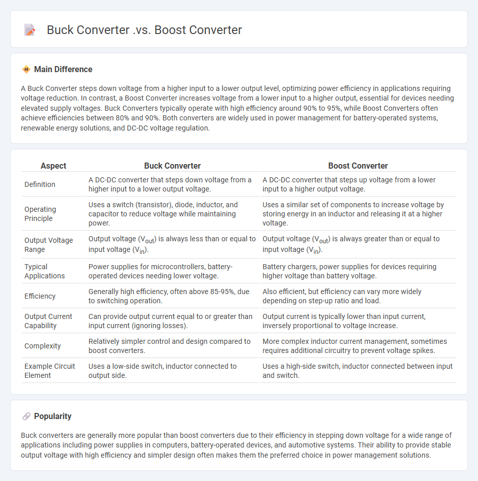
| Aspect | Buck Converter | Boost Converter |
|---|---|---|
| Definition | A DC-DC converter that steps down voltage from a higher input to a lower output voltage. | A DC-DC converter that steps up voltage from a lower input to a higher output voltage. |
| Operating Principle | Uses a switch (transistor), diode, inductor, and capacitor to reduce voltage while maintaining power. | Uses a similar set of components to increase voltage by storing energy in an inductor and releasing it at a higher voltage. |
| Output Voltage Range | Output voltage (Vout) is always less than or equal to input voltage (Vin). | Output voltage (Vout) is always greater than or equal to input voltage (Vin). |
| Typical Applications | Power supplies for microcontrollers, battery-operated devices needing lower voltage. | Battery chargers, power supplies for devices requiring higher voltage than battery voltage. |
| Efficiency | Generally high efficiency, often above 85-95%, due to switching operation. | Also efficient, but efficiency can vary more widely depending on step-up ratio and load. |
| Output Current Capability | Can provide output current equal to or greater than input current (ignoring losses). | Output current is typically lower than input current, inversely proportional to voltage increase. |
| Complexity | Relatively simpler control and design compared to boost converters. | More complex inductor current management, sometimes requires additional circuitry to prevent voltage spikes. |
| Example Circuit Element | Uses a low-side switch, inductor connected to output side. | Uses a high-side switch, inductor connected between input and switch. |
Step-Down Conversion (Buck Converter)
A step-down converter, or buck converter, efficiently reduces high DC voltage to a lower level using a switching element, inductor, diode, and capacitor, enabling power regulation in electronics. The buck converter operates by rapidly switching the input voltage on and off, storing energy in the inductor and releasing it to the load at a lower voltage, achieving a conversion efficiency typically above 90%. Common applications include power supplies for microprocessors, battery chargers, and LED drivers where stable low voltage output is crucial. Using pulse-width modulation (PWM) control, the buck converter precisely regulates output voltage under varying load conditions and input voltages.
Step-Up Conversion (Boost Converter)
Step-up conversion, commonly implemented through a boost converter, increases input voltage to a higher output voltage by storing energy in an inductor and releasing it to the load. Key components include an inductor, a switch, a diode, and a capacitor, which work together to regulate voltage and current. Boost converters achieve efficiencies typically ranging from 80% to 95%, making them essential in applications such as battery-powered devices and renewable energy systems. Control methods often involve pulse-width modulation (PWM) to maintain desired voltage levels under varying load conditions.
Input-Output Voltage Relationship
The input-output voltage relationship in engineering systems often depends on the configuration of circuit elements such as resistors, capacitors, and inductors. In voltage divider circuits, the output voltage is a fraction of the input voltage, calculated using the ratio of resistor values. Operational amplifiers create precise voltage relationships through feedback mechanisms, allowing amplification or attenuation of input signals. Transformers adjust voltage levels in AC circuits based on the turns ratio of their coils, enabling efficient power distribution.
Efficiency and Power Loss
Efficiency in engineering measures the ratio of useful output energy to input energy, expressed as a percentage, reflecting how effectively a system converts energy. Power loss occurs primarily due to factors such as friction, resistance, and heat dissipation within mechanical and electrical components, leading to decreased performance and increased operating costs. For example, electric motors typically experience power losses ranging from 5% to 15%, with high-efficiency models achieving over 90% efficiency. Optimizing design, materials, and maintenance can significantly reduce power loss and enhance overall system efficiency.
Circuit Complexity and Applications
Circuit complexity measures the minimal resources required for computational circuits, including gate count and depth, to solve specific problems efficiently. Advances in circuit complexity have significantly influenced the design of integrated circuits, optimizing performance and reducing power consumption in engineering applications. Understanding NP-complete problems through circuit complexity theory helps develop approximation algorithms and heuristic models used in VLSI design and signal processing. Research continues to bridge theoretical limits with practical circuit engineering, enhancing scalability and fault tolerance in modern electronic systems.
Source and External Links
Boost converter vs Buck Converter? - EEVblog - A buck converter decreases voltage (Vout < Vin), while a boost converter increases voltage (Vout > Vin); they share common ground and output polarity, chosen based on application needs.
How Buck, Boost & Buck-Boost DC-DC Converters Work - YouTube - Buck converters step down voltage, boost converters step up voltage, and buck-boost converters can do both but invert the output voltage polarity.
Buck vs. Boost - Sunforge LLC - Buck converters reduce voltage while increasing current, suitable for stepping down from high voltage; boost converters increase voltage while decreasing current, used when input voltage is lower than required output.
FAQs
What is a buck converter?
A buck converter is a DC-DC power converter that steps down voltage from a higher input level to a lower output level with high efficiency.
What is a boost converter?
A boost converter is a DC-DC power converter that increases (steps up) input voltage to a higher output voltage while maintaining power efficiency.
How does a buck converter work?
A buck converter steps down voltage by rapidly switching a transistor on and off to control energy transfer through an inductor and capacitor, maintaining a lower, regulated output voltage.
How does a boost converter operate?
A boost converter operates by switching an inductor between a power source and a load, storing energy in the inductor during the switch-on phase, and releasing it at a higher voltage during the switch-off phase, regulated by a diode and a capacitor.
What are the key differences between buck and boost converters?
Buck converters step down voltage with higher efficiency, while boost converters step up voltage; buck converters conduct current during the switch ON state, boost converters store energy in an inductor and release it during the switch OFF state; buck converters have output voltage less than input voltage, boost converters have output voltage greater than input voltage.
Where are buck converters commonly used?
Buck converters are commonly used in power supply systems for voltage regulation in battery-powered devices, DC motor drives, renewable energy systems, and telecommunications equipment.
Where are boost converters typically applied?
Boost converters are typically applied in battery-powered devices, power supply systems, electric vehicles, and renewable energy systems to step up voltage efficiently.